|
|
Post by davbow on Aug 24, 2018 3:58:04 GMT 2
Does anyone have information about the connector on the GPS board?
Also, has anyone finished the GPS to completion?
TIA
DAvid
|
|
|
|
Post by username on Aug 24, 2018 4:23:00 GMT 2
Hi, i haven't finished it yet but im planning on using on of the extra connector on the arduino pcb for the gps. but you have to ask alb eagle for the pin out of it.
have you already completed the radio stack? it be great if you had the mobiflight file. thanks.
|
|
|
|
Post by AlbEagle on Aug 24, 2018 21:32:08 GMT 2
GPS Pinout, i posted the picture on the website as well. I will post the extra pinouts of the arduino boards too. 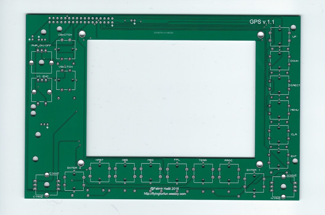 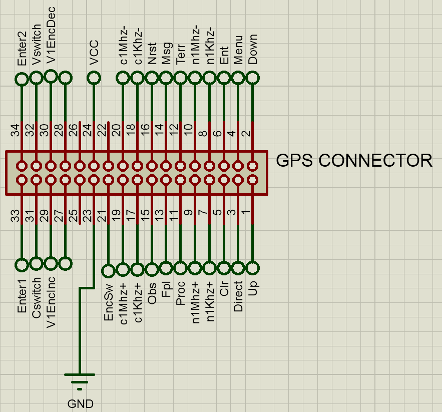 |
|
|
|
Post by davbow on Aug 25, 2018 0:44:34 GMT 2
So freakin' awesome! Thank you!
|
|
|
|
Post by hannes1 on Jul 5, 2019 11:23:47 GMT 2
Hello, do you have a drawing from GPS or have you already drawn a front panel and buttons? Many Thanks
|
|
|
|
Post by AlbEagle on Jul 6, 2019 13:14:21 GMT 2
Hello, do you have a drawing from GPS or have you already drawn a front panel and buttons? Many Thanks Not the front panel, but the buttons are in the radiostack buttons i think. Check those files. Buttons link |
|
|
|
Post by AlbEagle on Jul 6, 2019 13:59:21 GMT 2
Here is the gps stl, check and modify accordingly. Attachments:GPS faceplate.stl (68.34 KB)
|
|
|
|
Post by hannes1 on Jul 8, 2019 7:27:19 GMT 2
Thanks a lot for the .stl file. Can you send me another file in .dwg or .dxf or .stp? The faceplate is only 0.3mm thick. I have to make them thicker so that i can print. Thank you
|
|
|
|
Post by hannes1 on Jul 8, 2019 10:04:09 GMT 2
Hello, how is the display connected? on arduino or directly via HDMI to the graphics card? is it a normal screen, where you push the gps image of the Sim? Thank you
|
|
|
|
Post by hannes1 on Jul 9, 2019 8:54:00 GMT 2
Does anyone already have a Config for the Arduino of Mobiflight? Thank you
|
|
|
|
Post by AlbEagle on Jul 10, 2019 21:06:44 GMT 2
Thanks a lot for the .stl file. Can you send me another file in .dwg or .dxf or .stp? The faceplate is only 0.3mm thick. I have to make them thicker so that i can print. Thank you - Attached you will find two files (dwg and dxf) - Display is connected to PC and serves as a monitor so you can drag the GPS over to this 5 Inch display (you have to be careful when ordering the display as it should be able to connect to the PC as a monitor and not every Display does that). You connect the PCB pinouts directly to the Arduino and program them (for example with Mobiflight). - I don't have a config file as I have never finished the GPS (Purchased the wrong display and never got the chance to purchase another one) Attachments:gps.dwg (78 KB)
gps.dxf (79.74 KB)
|
|
|
|
Post by hannes1 on Jul 11, 2019 14:41:04 GMT 2
Thanks for the drawing. Are components such as resistors to be installed on the board? If yes, which? Do you have a fitting plan?
|
|
|
|
Post by hannes1 on Jul 13, 2019 19:28:12 GMT 2
does the pwr on / off have to be connected directly to the power from the display or to the arduino?
|
|
|
|
Post by hannes1 on Jul 15, 2019 7:47:38 GMT 2
Thanks in advance for the files from the GPS. I think I have found a mistake. On the board, the buttons CLR, PROC and FPL have no connection to Ground. I installed here wire hanger. Can you confirm it? Two more questions. I do not understand the function or wiring of PWR On / OFF. Can you explain that to me. And which GPS is your layout modeled? So I can arrange the key names correctly and can find the offsets for P3D. Many Thanks
|
|
|
|
Post by hector on Jul 17, 2019 21:19:48 GMT 2
Thanks in advance for the files from the GPS. I think I have found a mistake. On the board, the buttons CLR, PROC and FPL have no connection to Ground. I installed here wire hanger. Can you confirm it? Two more questions. I do not understand the function or wiring of PWR On / OFF. Can you explain that to me. And which GPS is your layout modeled? So I can arrange the key names correctly and can find the offsets for P3D. Many Thanks Hi I´m looking the same |
|


