willh
New Member

Posts: 16
|
Post by willh on Oct 19, 2023 23:33:47 GMT 2
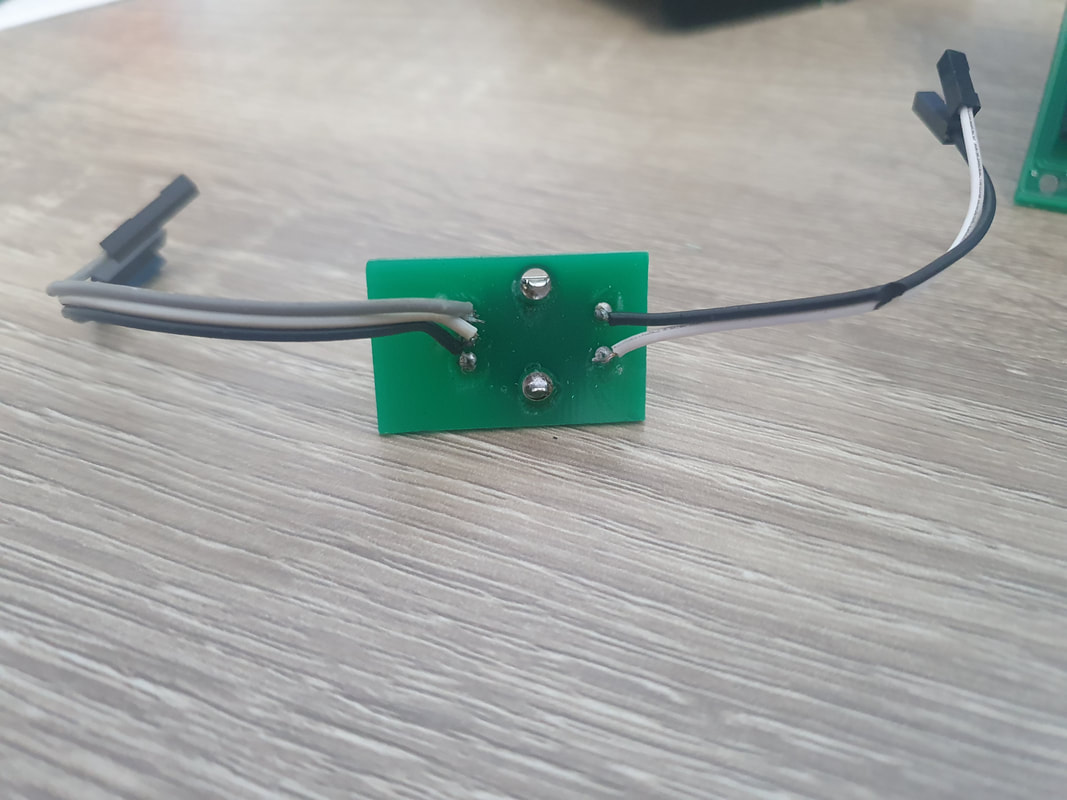
I am almost done with the FCU build! I need some help wiring the encoders tho.
Maybe I missed it but is there a wiring diagram somewhere? Each encoder has three wires soldered to them but which is the +, ground and -?
No matter which order I try MobiFlight doesn't recognize the change in the log..
|
|
|
|
Post by AlbEagle on Oct 20, 2023 8:00:17 GMT 2
Hi there, The encoder has three wires for the rotary knob and two wires for the push button. From the three wires, the middle one is GND, the other two you can swap depending on the direction you want to change values (increase or decrease) which by the way you can also change in mobiflight. Please check if the wires are soldered properly, a multimeter would help. Please also check if you have soldered all resistors (in this case some 10k resistors which are used as pull down resistors with the encoders). For example, for the IAS Knob, you need to have soldered R27 and R28.   |
|
willh
New Member

Posts: 16
|
Post by willh on Oct 20, 2023 15:57:37 GMT 2
|
|
|
|
Post by AlbEagle on Oct 20, 2023 18:13:23 GMT 2
Hi, Those LED's are meant to stay on. The ones circled are always on because they light the altitude symbols, and the rest are for backlighting purposes which also stay on.  Have you soldered an on/off switch there or have you shortened the pins  also, how did you connect the arduino, can you show a picture with the arduino and the encoders connected from the backside. Also there is actually an order I power on the PCB's, first put the power supply in (+5V), than connect the arduino and at the end I open flight simulator and mobiflight. Regards AlbEagle |
|
willh
New Member

Posts: 16
|
Post by willh on Oct 20, 2023 18:34:02 GMT 2
I didn't add a power switch to the board.. Didn't know I needed one. Here are a few more pictures. I'll have to put the encoders back on in a little bit. I took them off to make looking at the pictures easier. ibb.co/dmG9LQvibb.co/8KPKNPdibb.co/YjfC2DMNot on purpose but that's the same way I power the board up. Figured it needed power first and then plug in to the computer. |
|
|
|
Post by AlbEagle on Oct 20, 2023 19:02:28 GMT 2
You need to solder an on/off switch and LED  or just solder the two pins together.  Regards AlbeEagle |
|
willh
New Member

Posts: 16
|
Post by willh on Oct 20, 2023 20:22:02 GMT 2
I jumped the two ON pins and added an LED. I plugged in all the encoders and once I turned it resistors on R32, R31, R30, R29, R28 and R27 started smoking.
I unplugged the encoders except the VS encoder and replaced R32, R31 and the left shift register (just guessing with replacing the register). Turned on the board and R32 started smoking again. Seems like there is a short but without knowing what runs what it's hard for me to troubleshoot. Any ideas?
Pulled all the caps off the board and still short.. What chips are on the 10k line?
|
|
|
|
Post by AlbEagle on Oct 20, 2023 22:01:26 GMT 2
I am not at home right now so I can't check, but it looks like the encoder resistors. As soon as i get home I will check. Just to be sure, you are using 5V right?
|
|
willh
New Member

Posts: 16
|
Post by willh on Oct 20, 2023 22:53:51 GMT 2
I am not at home right now so I can't check, but it looks like the encoder resistors. As soon as i get home I will check. Just to be sure, you are using 5V right? They are the encoder resistors. Looks like it’s the encoders themselves. I ended up taking all the caps and registers off the board and there was still a short. So I checked the encoders and all four are shorted. I ordered new encoders so I’ll know more tomorrow when I get the new encoders. |
|
|
|
Post by AlbEagle on Oct 20, 2023 23:03:26 GMT 2
Looks that way to me too, I was checking the schematics and there is no other explanation. Please let me know once you have changed the encoders.
|
|
willh
New Member

Posts: 16
|
Post by willh on Oct 22, 2023 0:47:53 GMT 2
That's what it was, all four encoders were bad.
Thanks China.
Soldered some leads to one of the new encoder and plugged it into VS, it's working fine.
|
|
willh
New Member

Posts: 16
|
Post by willh on Oct 22, 2023 18:28:28 GMT 2
I missed the rotary switch.. Do I need to get the 2 Pole 4? Also, what on/off switch do you recommend?
|
|
|
|
Post by AlbEagle on Oct 22, 2023 19:05:16 GMT 2
|
|
willh
New Member

Posts: 16
|
Post by willh on Oct 22, 2023 22:10:08 GMT 2
The saga continues.. The resistors for the Heading encoder keep burning. It’s not the encoder. Something is causing an over current event to these resistors. What chip are these resistors tied to? Is it a register or max chip?
|
|
|
|
Post by AlbEagle on Oct 22, 2023 22:49:49 GMT 2
Hi,
Here you will find the resistors, values and to what they are connected to.
Sorry check the other post, there was a mistake.
|
|